So to start of i have already covered a bit of this topic in a previous post about Modeling languages. So if you don’t know what modeling languages are then i recommend reading that post before this one.
As I’ve said in my previous posts UML (Unified modeling language) is a graphical modeling language that can be used as a standardized way of visualizing software architecture. UML diagrams can be dived into two main categories: structural diagrams that focus on the organization of the system and the behavioral diagrams which displays the dynamic behavior of the system.
So why do you need UML?
In software projects with multiple stakeholders and developers involved you need a efficient and simple way of communicating ideas. This can be solved by using UML diagrams. They give a visual representation of the software architecture, which helps developers and people with limited programming knowledge to get a deeper understanding of the software. The main reason why I use these diagrams though is because it help me and my team to discover and analyze problems with the code in earlier stages when they are easier to resolve.
There are many different types of UML diagrams out there, here are some common examples:
Class diagrams
The class diagram is commonly used for displaying the classes of a software. It’s a structural diagram that show the attributes and methods of the classes and how they are associated with each other through inheritance and aggregations. As I said in my previous post it’s a very useful tool for modeling both large and small software systems. They can be used to avoid problems such as code duplication and redundancy by making it clear which class or object should do what and what variables they should store.

Sequence Diagrams
Sequence diagrams are used to display interactions between objects or classes in the order in which they take place. They describe how and in what order the components in a system function. These diagrams are primarily used by business professionals and software developers to document and understand processes or to understand the requirements for new or existing system.
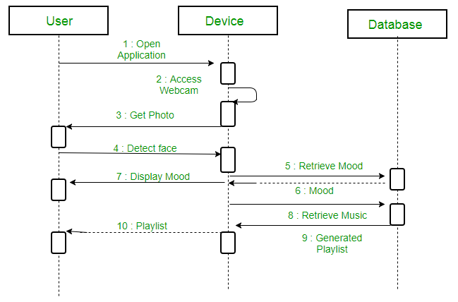
In the top of the diagram above we have the internal objects of the system known as lifelines, which consist of device and database. Then we also have external objects such as user of the system which are referred to as actors. Between all these objects there are arrows going back and forth, these are called messages. They signify the interactions between the objects. In this diagram you should not focus on what messages exist but rather in what order they are in. This site has a more detailed explanation
Object Diagram
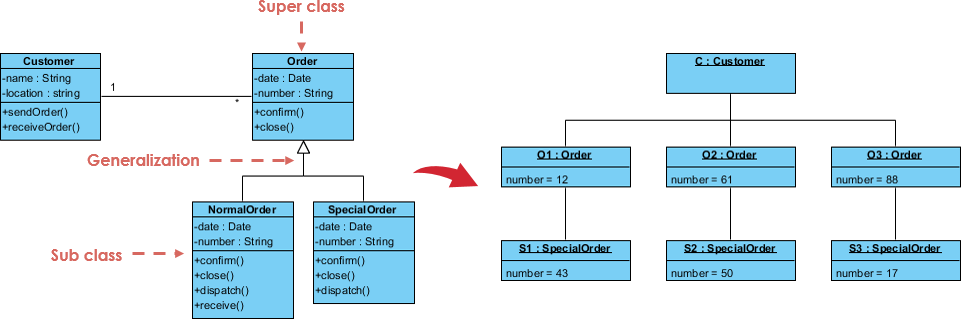
Object diagram looks very similar to a class diagrams. But instead of a only displaying the static classes, object diagrams also displays instantiated classes (Objects). This means that the classes can be displayed with their values and names at a particular period. Normally when modeling classes you would use class diagrams, but if there are many complex classes with e.g. recursive relationships involved then object diagrams might give a better representation.
If you want to learn more about UML diagrams then you should check out this site.

Lämna en kommentar